Gas compressor
A gas compressor is a mechanical device that increases the pressure of a gas by reducing its volume.
Compressors are similar to pumps: both increase the pressure on a fluid and both can transport the fluid through a pipe. As gases are compressible, the compressor also reduces the volume of a gas. Liquids are relatively incompressible, so the main action of a pump is to pressurize and transport liquids.
Contents |
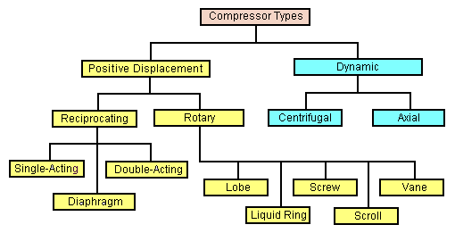
Types of compressors
The main types of gas compressors are illustrated and discussed below:
Centrifugal compressors
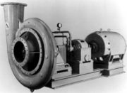
Centrifugal compressors use a rotating disk or impeller in a shaped housing to force the gas to the rim of the impeller, increasing the velocity of the gas. A diffuser (divergent duct) section converts the velocity energy to pressure energy. They are primarily used for continuous, stationary service in industries such as oil refineries, chemical and petrochemical plants and natural gas processing plants.[1][2][3] Their application can be from 100 horsepower (75 kW) to thousands of horsepower. With multiple staging, they can achieve extremely high output pressures greater than 10,000 psi (69 MPa).
Many large snowmaking operations (like ski resorts) use this type of compressor. They are also used in internal combustion engines as superchargers and turbochargers. Centrifugal compressors are used in small gas turbine engines or as the final compression stage of medium sized gas turbines. Sometimes the capacity of the compressors is written in NM3/hr. Here 'N' stands for normal temperature pressure (20oC and 1 atm ) for example 5500 NM3/hr.
Diagonal or mixed-flow compressors
Diagonal or mixed-flow compressors are similar to centrifugal compressors, but have a radial and axial velocity component at the exit from the rotor. The diffuser is often used to turn diagonal flow to
Axial-flow compressors

Axial-flow compressors are dynamic rotating compressors that use arrays of fan-like airfoils to progressively compress the working fluid. They are used where there is a requirement for a high flow rate or a compact design.
The arrays of airfoils are set in rows, usually as pairs: one rotating and one stationary. The rotating airfoils, also known as blades or rotors, accelerate the fluid. The stationary airfoils, also known as stators or vanes, decelerate and redirect the flow direction of the fluid, preparing it for the rotor blades of the next stage.[1] Axial compressors are almost always multi-staged, with the cross-sectional area of the gas passage diminishing along the compressor to maintain an optimum axial Mach number. Beyond about 5 stages or a 4:1 design pressure ratio, variable geometry is normally used to improve operation.
Axial compressors can have high efficiencies; around 90% polytropic at their design conditions. However, they are relatively expensive, requiring a large number of components, tight tolerances and high quality materials. Axial-flow compressors can be found in medium to large gas turbine engines, in natural gas pumping stations, and within certain chemical plants.
Reciprocating compressors
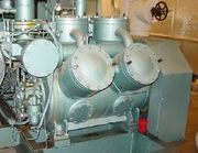
Reciprocating compressors use pistons driven by a crankshaft. They can be either stationary or portable, can be single or multi-staged, and can be driven by electric motors or internal combustion engines.[1][4][5] Small reciprocating compressors from 5 to 30 horsepower (hp) are commonly seen in automotive applications and are typically for intermittent duty. Larger reciprocating compressors well over 1,000 hp (750 kW) are commonly found in large industrial and petroleum applications. Discharge pressures can range from low pressure to very high pressure (>18000 psi or 180 MPa). In certain applications, such as air compression, multi-stage double-acting compressors are said to be the most efficient compressors available, and are typically larger, and more costly than comparable rotary units.[6] Another type of reciprocating compressor is the swash plate compressor, which uses pistons which are moved by a swash plate mounted on a shaft.
Household, home workshop, and smaller job site compressors are typically reciprocating compressors 1 1/2 hp or less with an attached receiver tank.
Rotary screw compressors
Rotary screw compressors use two meshed rotating positive-displacement helical screws to force the gas into a smaller space.[1][7][8] These are usually used for continuous operation in commercial and industrial applications and may be either stationary or portable. Their application can be from 3 horsepower (2.2 kW) to over 1,200 horsepower (890 kW) and from low pressure to moderately high pressure (>1,200 psi or 8.3 MPa).
Rotary vane compressors
Rotary vane compressors consist of a rotor with a number of blades inserted in radial slots in the rotor. The rotor is mounted offset in a larger housing which can be circular or a more complex shape. As the rotor turns, blades slide in and out of the slots keeping contact with the outer wall of the housing.[1] Thus, a series of decreasing volumes is created by the rotating blades. Rotary Vane compressors are, with piston compressors one of the oldest of compressor technologies.
With suitable port connections, the devices may be either a compressor or a vacuum pump. They can be either stationary or portable, can be single or multi-staged, and can be driven by electric motors or internal combustion engines. Dry vane machines are used at relatively low pressures (e.g., 2 bar or 200 kPa; 29 psi) for bulk material movement whilst oil-injected machines have the necessary volumetric efficiency to achieve pressures up to about 13 bar (1,300 kPa; 190 psi) in a single stage. A rotary vane compressor is well suited to electric motor drive and is significantly quieter in operation than the equivalent piston compressor.
Rotary vane compressors can have mechanical efficiencies of about 90%.[9]
Scroll compressors

A scroll compressor, also known as scroll pump and scroll vacuum pump, uses two interleaved spiral-like vanes to pump or compress fluids such as liquids and gases. The vane geometry may be involute, archimedean spiral, or hybrid curves.[10][11][12] They operate more smoothly, quietly, and reliably than other types of compressors in the lower volume range
Often, one of the scrolls is fixed, while the other orbits eccentrically without rotating, thereby trapping and pumping or compressing pockets of fluid or gas between the scrolls.
This type of compressor was used as the supercharger on Volkswagen G60 and G40 engines in the early 1990s.
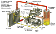
Diaphragm compressors
A diaphragm compressor (also known as a membrane compressor) is a variant of the conventional reciprocating compressor. The compression of gas occurs by the movement of a flexible membrane, instead of an intake element. The back and forth movement of the membrane is driven by a rod and a crankshaft mechanism. Only the membrane and the compressor box come in contact with the gas being compressed.[1]
Diaphragm compressors are used for hydrogen and compressed natural gas (CNG) as well as in a number of other applications.
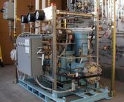
The photograph included in this section depicts a three-stage diaphragm compressor used to compress hydrogen gas to 6,000 psi (41 MPa) for use in a prototype compressed hydrogen and compressed natural gas (CNG) fueling station built in downtown Phoenix, Arizona by the Arizona Public Service company (an electric utilities company). Reciprocating compressors were used to compress the natural gas.
The prototype alternative fueling station was built in compliance with all of the prevailing safety, environmental and building codes in Phoenix to demonstrate that such fueling stations could be built in urban areas.
Temperature
Compression of a gas naturally increases its temperature.
In an attempt to model the compression of gas, there are two theoretical relationships between temperature and pressure in a volume of gas undergoing compression (isothermal and adiabatic). Although neither of them model the real world exactly, each can be useful for analysis. A third method (polytropic) measures real-world results.
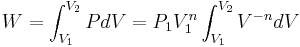
In general, the energy required for adiabatic compression can be calculated as follows:
 where
where
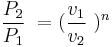
so
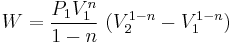
with n taking different values for different compression processes (see below).
- Adiabatic - This model assumes that no energy (heat) is transferred to or from the gas during the compression, and all supplied work is added to the internal energy of the gas, resulting in increases of temperature and pressure. Theoretical temperature rise is[13]:
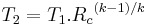 with T1 and T2 in degrees Rankine or kelvins, and k = ratio of specific heats (approximately 1.4 for air). Rc is the compression ratio; being the absolute outlet pressure divided by the absolute inlet pressure. The rise in air and temperature ratio means compression does not follow a simple pressure to volume ratio. This is less efficient, but quick. Adiabatic compression or expansion more closely model real life when a compressor has good insulation, a large gas volume, or a short time scale (i.e., a high power level). In practice there will always be a certain amount of heat flow out of the compressed gas. Thus, making a perfect adiabatic compressor would require perfect heat insulation of all parts of the machine. For example, even a bicycle tire pump's metal tube becomes hot as you compress the air to fill a tire. The relation between temperature and compression ratio described above means that the value of n for an adiabatic process is k (the ratio of specific heats).
- Isothermal - This model assumes that the compressed gas remains at a constant temperature throughout the compression or expansion process. In this cycle, internal energy is removed from the system as heat at the same rate that it is added by the mechanical work of compression. Isothermal compression or expansion more closely models real life when the compressor has a large heat exchanging surface, a small gas volume, or a long time scale (i.e., a small power level). Compressors that utilize inter-stage cooling between compression stages come closest to achieving perfect isothermal compression. However, with practical devices perfect isothermal compression is not attainable. For example, unless you have an infinite number of compression stages with corresponding intercoolers, you will never achieve perfect isothermal compression.
For an isothermal process, n is 1, so the value of the work integral for an isothermal process is:
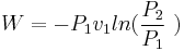
When evaluated, the isothermal work is found to be lower than the adiabatic work.
- Polytropic - This model takes into account both a rise in temperature in the gas as well as some loss of energy (heat) to the compressor's components. This assumes that heat may enter or leave the system, and that input shaft work can appear as both increased pressure (usually useful work) and increased temperature above adiabatic (usually losses due to cycle efficiency). Compression efficiency is then the ratio of temperature rise at theoretical 100 percent (adiabatic) vs. actual (polytropic). Polytropic compression will use a value of n between 0 (a constant-pressure process) and infinity (a constant volume process). For the typical case where an effort is made to cool the gas compressed by an approximately adiabatic process, the value of n will be between 1 and k.
Staged compression
In the case of centrifugal compressors, commercial designs currently do not exceed a compression ratio of more than a 3.5 to 1 in any one stage (for a typical gas). Since compression generates heat, the compressed gas is to be cooled between stages making the compression less adiabatic and more isothermal. The inter-stage coolers typically result in some partial condensation that is removed in vapor-liquid separators.
In the case of small reciprocating compressors, the compressor flywheel may drive a cooling fan that directs ambient air across the intercooler of a two or more stage compressor.
Because rotary screw compressors can make use of cooling lubricant to remove the heat of compression, they very often exceed a 9 to 1 compression ratio. For instance, in a typical diving compressor the air is compressed in three stages. If each stage has a compression ratio of 7 to 1, the compressor can output 343 times atmospheric pressure (7 x 7 x 7 = 343 atmospheres). (343 atm/34.8 MPa; 5.04 ksi)
Prime movers
There are many options for the "prime mover" or motor which powers the compressor:
- gas turbines power the axial and centrifugal flow compressors that are part of jet engines
- steam turbines or water turbines are possible for large compressors
- electric motors are cheap and quiet for static compressors. Small motors suitable for domestic electrical supplies use single phase alternating current. Larger motors can only be used where an industrial electrical three phase alternating current supply is available.
- diesel engines or petrol engines are suitable for portable compressors and support compressors used as superchargers from their own crankshaft power. They use exhaust gas energy to power turbochargers
Applications
Gas compressors are used in various applications where either higher pressures or lower volumes of gas are needed:
- in pipeline transport of purified natural gas to move the gas from the production site to the consumer. Often, the compressor in this application is driven by a gas turbine which is fueled by gas bled from the pipeline. Thus, no external power source is necessary.
- in petroleum refineries, natural gas processing plants, petrochemical and chemical plants, and similar large industrial plants for compressing intermediate and end product gases.
- in refrigeration and air conditioner equipment to move heat from one place to another in refrigerant cycles: see Vapor-compression refrigeration.
- in gas turbine systems to compress the intake combustion air
- in storing purified or manufactured gases in a small volume, high pressure cylinders for medical, welding and other uses.
- in many various industrial, manufacturing and building processes to power all types of pneumatic tools.
- as a medium for transferring energy, such as to power pneumatic equipment.
- in pressurised aircraft to provide a breathable atmosphere of higher than ambient pressure.
- in some types of jet engines (such as turbojets and turbofans) to provide the air required for combustion of the engine fuel. The power to drive the combustion air compressor comes from the jet's own turbines.
- in SCUBA diving, hyperbaric oxygen therapy and other life support devices to store breathing gas in a small volume such as in diving cylinders.[14][15]
- in submarines, to store air for later use in displacing water from buoyancy chambers, for adjustment of depth.
- in turbochargers and superchargers to increase the performance of internal combustion engines by increasing mass flow.
- in rail and heavy road transport to provide compressed air for operation of rail vehicle brakes or road vehicle brakes and various other systems (doors, windscreen wipers, engine/gearbox control, etc.).
- in miscellaneous uses such as providing compressed air for filling pneumatic tires.
- in the case of the fire piston and the heat pump, the desired outcome is the temperature rise of the gas, and compressing the gas is only a means to that end.
See also
|
|
References
- ↑ 1.0 1.1 1.2 1.3 1.4 1.5 Perry, R.H. and Green, D.W. (Editors) (2007). Perry's Chemical Engineers' Handbook (8th ed.). McGraw Hill. ISBN 0-07-142294-3.
- ↑ Dixon S.L. (1978). Fluid Mechanics, Thermodynamics of Turbomachinery (Third ed.). Pergamon Press. ISBN 0-08-022722-8.
- ↑ Aungier, Ronald H. (2000). Centrifugal Compressors A Strategy for Aerodynamic design and Analysis. ASME Press. ISBN 0-7918-0093-8.
- ↑ Bloch, H.P. and Hoefner, J.J. (1996). Reciprocating Compressors, Operation and Maintenance. Gulf Professional Publishing. ISBN 0-88415-525-0.
- ↑ Reciprocating Compressor Basics Adam Davis, Noria Corporation, Machinery Lubrication, July 2005
- ↑ Introduction to Industrial Compressed Air Systems
- ↑ Screw Compressor Describes how screw compressors work and include photographs.
- ↑ Technical Centre Discusses oil-flooded screw compressors including a complete system flow diagram
- ↑ Mattei Compressors
- ↑ Tischer, J., Utter, R: “Scroll Machine Using Discharge Pressure For Axial Sealing,” U.S. Patent 4522575, 1985.
- ↑ Caillat, J., Weatherston, R., Bush, J: “Scroll-Type Machine With Axially Compliant Mounting,” U.S. Patent 4767293, 1988.
- ↑ Richardson, Jr., Hubert: “Scroll Compressor With Orbiting Scroll Member Biased By Oil Pressure,” U.S. Patent 4875838, 1989.
- ↑ Perry's Chemical Engineer's Handbook 8th edition Perry, Green, page 10-45 section 10-76
- ↑ Millar IL; Mouldey PG (2008). "Compressed breathing air – the potential for evil from within.". Diving and Hyperbaric Medicine. (South Pacific Underwater Medicine Society) 38: 145–51. http://archive.rubicon-foundation.org/7964. Retrieved 2009-02-28.
- ↑ Harlow, V (2002). Oxygen Hacker's Companion. Airspeed Press. ISBN 0967887321.